Disclaimer
All the information you need to remove the questions before manufacture.
When you place a print order with 3DPRINTUK we want you to be confident that you’re making an informed decision about your print order. This page is our pre-print checklist pointing out all the potential problems that you should be aware of before agreeing to our T&C’s.
If nothing else, by the time you’ve read all this you’ll be a guru of SLS 3D Printing.

Section 1: Technical Details
1.1 Curved big flat prints
1.2 Thin walls
1.3 Holes
1.4 Part Orientation
1.5 Stepping
1.6 Shrinkage
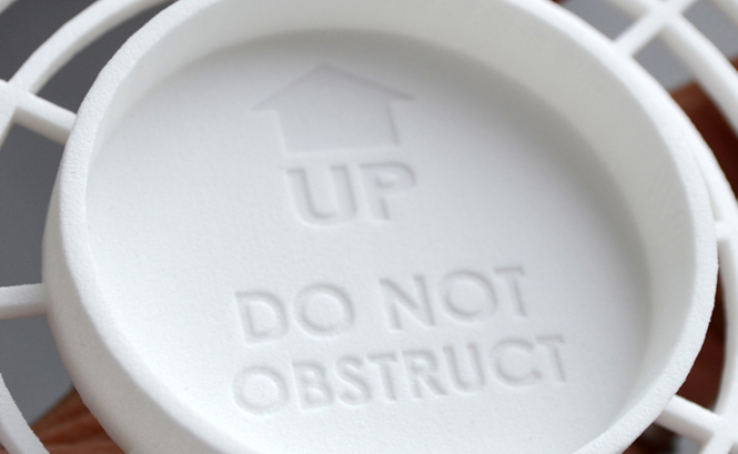
1.7 Text & Surface detail
Section 2: The way it looks
2.1 Polisher Damage
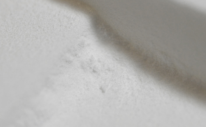
2.2 Powder Residue
2.3 Imperfections
2.4 Colour
2.5 Shot Peened Damage
Section 3: STL file settings
3.1 High File Resolution
3.2 Scales
3.3 Sprue Parts
3.4 Nest Parts
3.5 Poor File Quality
3.6 Tolerance for fitment
3.7 Moving Parts
Section 4: Order Details
4.1 File Fixing
4.2 Pricing
4.3 Intellectual Property
4.4 Lead times
4.5 Hollow/Solid Parts & Weight
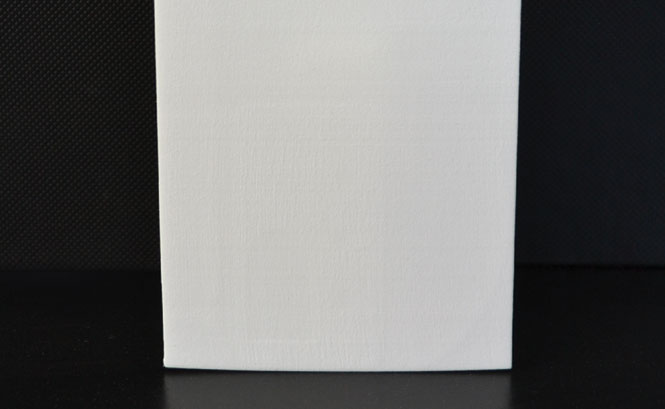
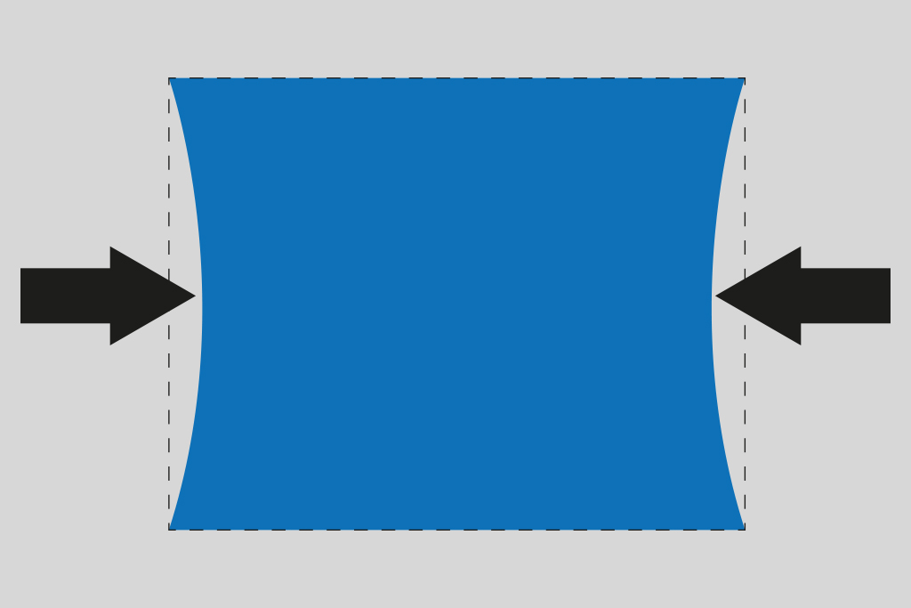
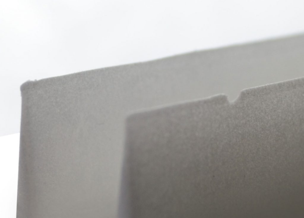
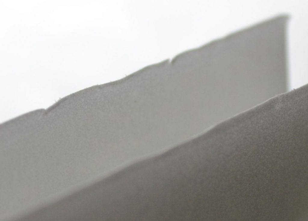
1.1 Curve and Warping on big flat prints
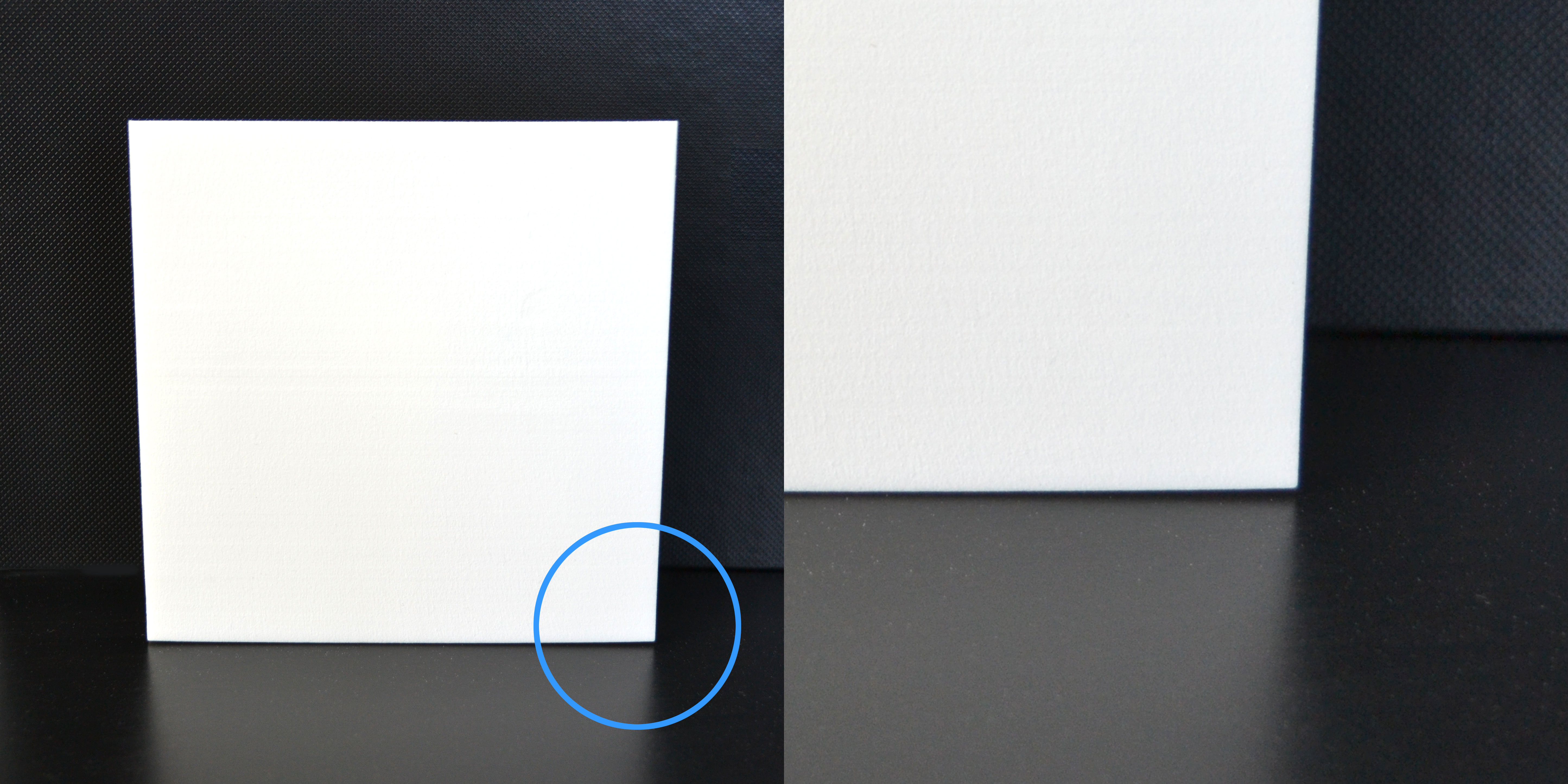
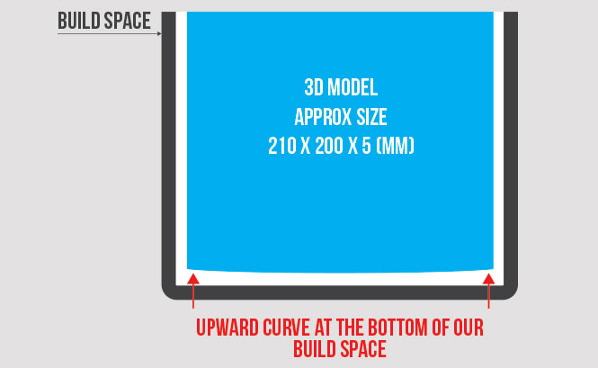
Curve: By far the biggest problem we face is printing big thin flat parts. As you can see from the image the very bottom of the piece is ever so slightly curved and does not sit flat on the table. This is down to shrinkage caused when the part cools down but will only effect the side closest to the bottom of our build space.
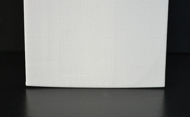
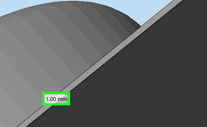
Below: A similar part but only 2mm thick, as a result, you can see more curving in the model on the bottom face.
Warping: As with any heat process that is used to make flat parts, warping can be an issue. If you have large thin flat parts then it is likely that some areas will cool faster than others and this shrink at different rates – i.e. if you’re making an A4 sized sheet that is 1mm thin, you’re likely to end up with a Pringle.
We combat this with a post process we do in house. This involves reheating the part and letting is cool clamped into position. We can only do this on parts that we are able to clamp so not all can be treated in this way. We’ll always try to warn you if there is the potential for it to warp, and we’ll make sure we do everything in our power for it not to do this. You must remember that if it does this with us, it is likely that it will do it with other processes!
Parts that are affected by this:
- Rectangular parts with flat edges on all sides. Larger objects are effected more.
Parts are guaranteed to a minimum wall thickness of 1 mm. We will print things thinner than 1 mm, but it is at your own risk. If these break in our hands, your hands, during delivery, or lost during the cleaning process, it will not be covered or re printed for free. Although, we do our best to check over every single model for printing, sometimes thinner parts can be missed, 3DPRINTUK is not held responsible if the parts are missed and printed anyway which results in a failed or broken part.
We try to clean every part of every model we print, but it’s only human that we may miss the odd one when there are hundreds of models to clean every day. The powder should come loose if you give it a poke with a needle or something similar. Long thin holes can be a bit stubborn and in some cases designing in a ‘drain’ type hole half way along the part can aid in getting the powder out.

Small holes
Roundness – Holes facing up the Z axis are generally quite round as the laser can draw a pretty good circle, but holes less that 2mm can get powder blocked inside. Though the powder has not been melted, it may have been heated enough for it to become a bit stubborn! The best with to do is put a drill bit down it when you receive it.
Holes facing across the Z axis tend to be elliptical, especially when small (<5mm). This is because you are effectively building the hole from straight lines (the layers), so it is impossible to get a perfect circle. Imagine you are building a circle out of Lego and you’ll get the idea. Holes tend to be more elliptical on the top than on the bottom as the laser cuts deeper through virgin powder than it does through sintered powder. We combat this with something called Z-compensation which raises the downward surfaces up by a few tenths of a millimeter but this is still not perfect.
Again, the best way to combat this is to put a drill bit through the holes once you receive them.
Deep Holes
Small diameter holes that run deep into a solid part tend to get clogged with powder as the heat from the solid part of the model radiates out and makes the powder in the holes pretty tough to remove. This can be a real problem with long twisting holes with a <5mm diameter. There is not really much we can do for these sadly.
For long straight holes, just as before, run a drill bit through and you should be fine.
Parts that are affected by this:
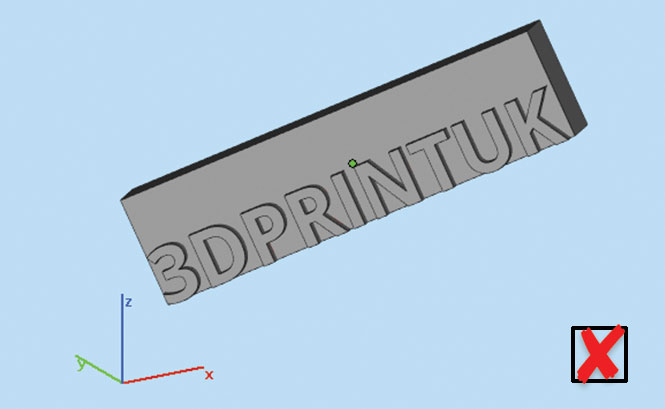
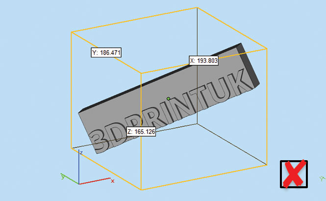
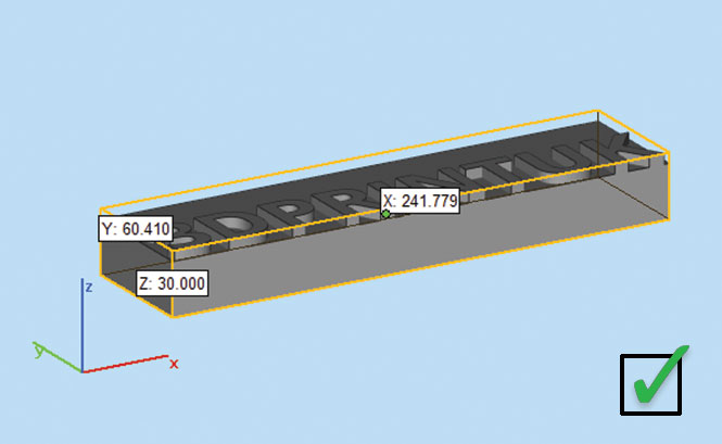
Part orientation is important for two reasons. The first and most important in that it will determine your x,y,z bounding box, which we will use to quote your print.
In the example below you can see the same part oriented in two ways. The left column shows a part that has been sent to us at an angle in the 3D space. As you can see in the image below the bounding box is a lot bigger than it needs to be and therefore the print cost will b a lot more expensive.
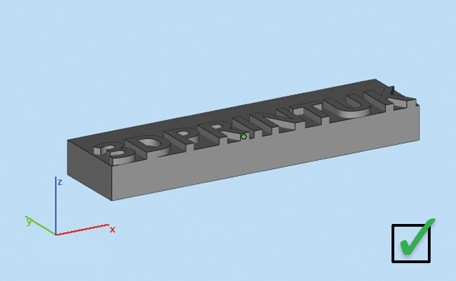
The right column shows the same part placed flat on the x,y axis which means that it bounding box (image below) is a lot small and therefore cheaper to print.
It is your job to make sure your part is orientated in the correct way before it is sent to us.
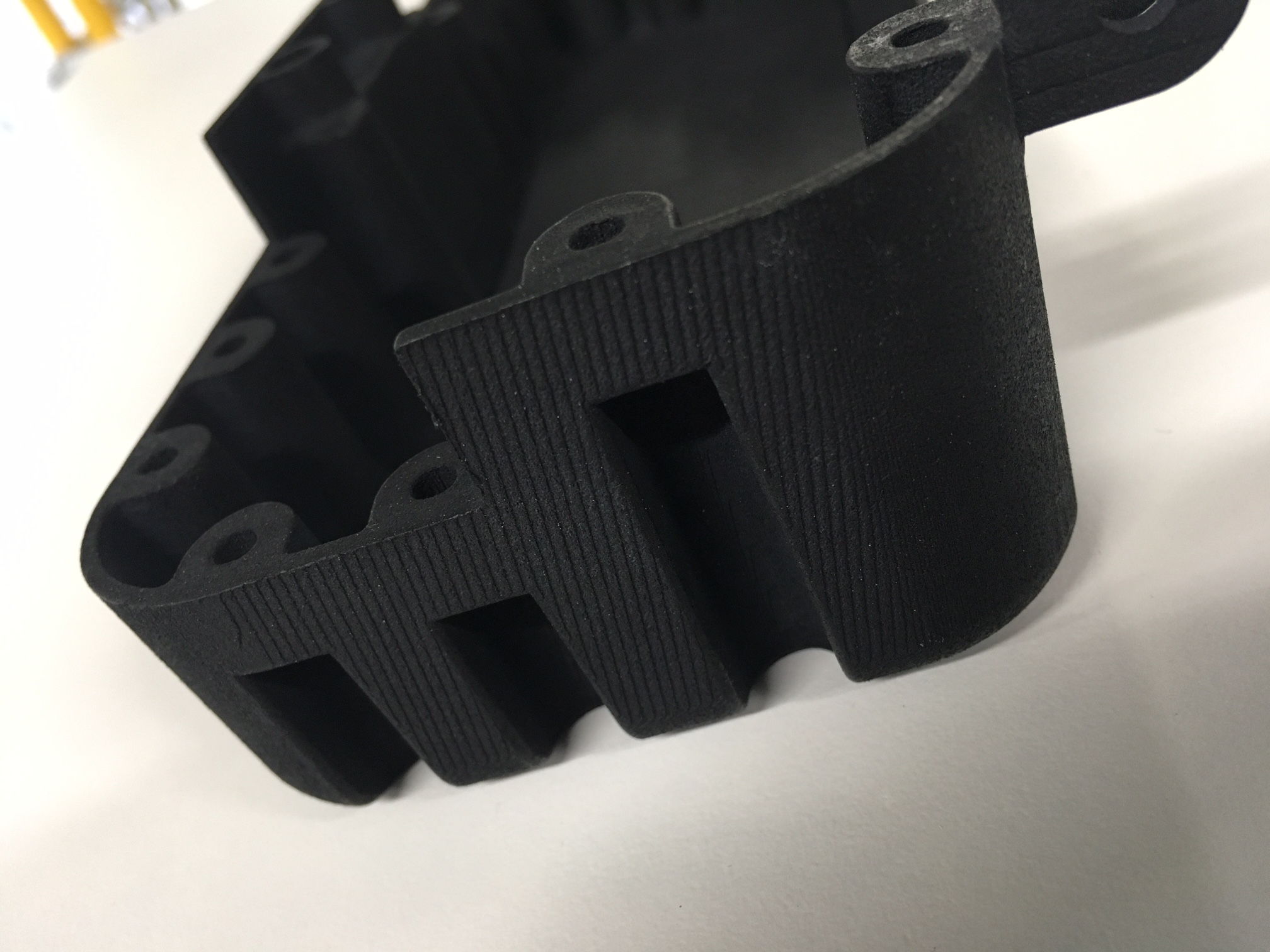
We orient every part in a way that gives you the best possible result rather than the most efficient for our build. This means that we virtually eliminate the layers on the model. We use a layer blending technique that means that only the very near horizontal lines will show up on one side, we always make this side the bottom so you don’t have to see them.
If you look at the example on the the right, the top of the platform is showing distinct stepping… to avoid this we would orientate the model upset side for printing.
We automatically calculate in the shrinkage amounts into the builds before we print. These are relatively complex as the lower half of the build can be hot for as much as 24 hours longer than the top. This means that for larger objects will have been cooling for longer at the bottom than they will at the top. Most of the shrinkage rates are calculated in, so you cannot notice for many parts, but if you have large parts that are spanning the build, especially rectangular items.
This can cause two types of problem:
1. Very thick parts shrinking excessively
If you have very large areas of model per layer (8-10cm diameter plus) there is a large amount of hotter melted powder. This is likely to contract more than thinner parts. To combat this we hollow the parts, but leave the unmelted powder locked inside with a wall thickness of about 5mm. This results in a solid part that feels and weighs the same as a solid part and still has a lot of strength yet does not shrink as much as if it were completely solid. In some cases we build spars to maintain the shape if required.
Parts that are affected by this:
- Thick solid parts with a greater diameter of 10cm
The natural surface finish is smooth, but has a powdery feel to it. This is comparable with an extra strong mint. With our free polishing service you get a far smoother finish for no extra cost – this is a finish comparable to a Soft Mint/Mentos.
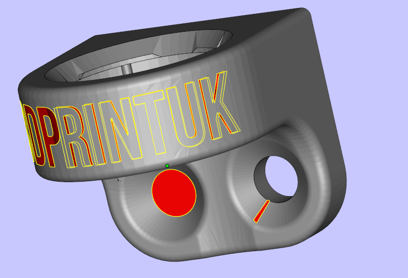
If you have embossed or engraved details such as logo’s or artwork, we have minimum guaranteed surface detail of 0.4mm. It is likely that items will be visible if they are less than this, but we cannot guarantee clarity below that.
Very small surface details that are below our minimum are not likely to come out. We have a recommended minimum of 0.5mm – below this and it’s at your own risk!
When polishing parts that have a tapered edge or unsupported walls, under 1mm, please be aware that it is highly likely that the part will be damaged during the vibro-polishing process. Unless it’s absolutely necessary to take this risk, we would advise not to polish that part. We recommend you thicken walls/end of the taper to a minimum of 1.5mm but we cannot guarantee that anything will survive below 2mm.
We know that not everyone likes the look and feel of a freshly printed SLS part as much as we do. That’s why we provide a free vibro polishing service for all orders.*
Make sure you read everything below about what to expect and also note that the process will add at least 1 extra day to your lead time**. The offer is subject to availability and the polishing queue will use the same priority service used for print orders, i.e. Express orders will be polished before Economy orders if capacity is tight.
*The maximum part size for polishing is approx: 150mm x 75mm x 75mm. If your model is nearing these dimensions we will let you know if it will be possible to polish.
*We will use our discretion when polishing small items and parts with extreme detail and thin walls.
**Large volume orders can take a few days due to the capacity of the polisher.
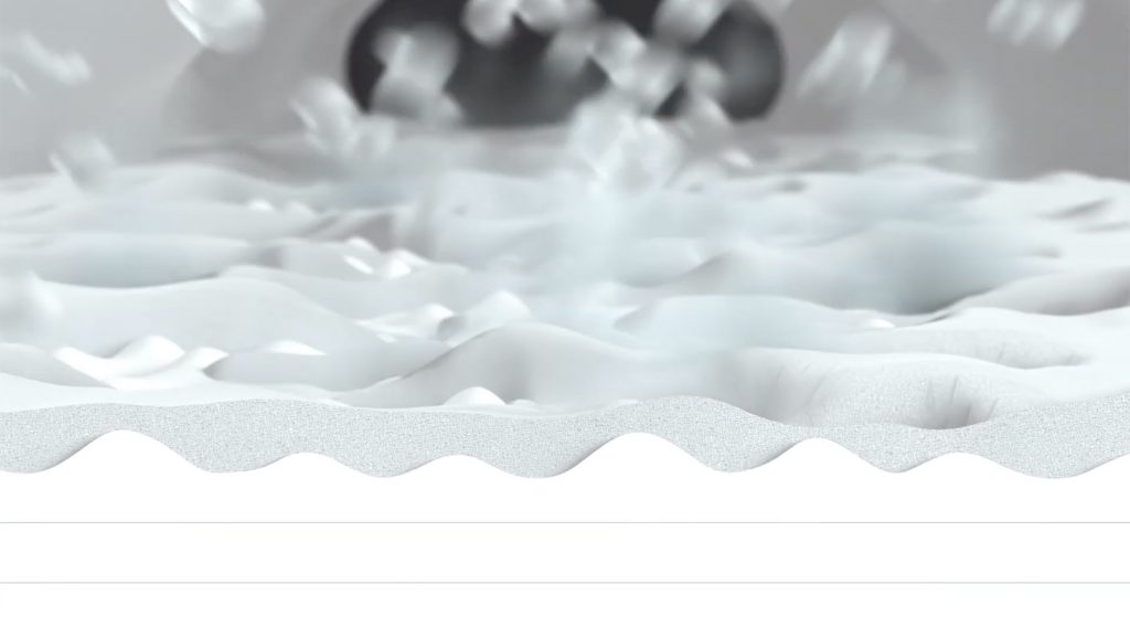
You’ll probably notice a small amount of white powder coming off the print when you touch it. Unfortunately this is part and parcel of the process but this thin layer of residual powder can be easily removed with water and a bit of soap. You can use a coarse brush if you want it really clean. The material may feel porous but its only the outer 0.2-0.3mm that will retain any moisture and this will dry out very quickly. Alternatively you could have the models polished for free using our polishing service.
Although rare, minor imperfections my be possible due the heat process and the recycling of nylon powder- this can include small traces of contamination ie dust. Even though we thoroughly clean our machines after every print and filter the powder many times over. It is still possible for the odd particle to get through.
rippling/orange peel on slopping surfaces.
minor impact marks/ scarring – scuff mark from contact with other parts usually during the polishing process
Triangulation on flat surfaces – This is caused when vectors that appear to be a flat surface are actually on different heights. The printers are accurate to o.1mm so if something is out that is what will get printed.

The material is a brilliant white in its natural form, but can be dyed Carbon Black for an additional 10%
UV Degradation – No noticeable physical degradation has been observed to the properties of the part other than a slight yellowing of the colour. All our oldest samples still appear to have the strength they had when new.
RIGHT: You can see the effect of UV light on the nylon we use. The snake skull is over 5 years old and has been sitting in direct sunlight since it was printed. The other part in the background is a new print.

The minimum thickness of parts for our Shot Peened finish is 1.5mm.
When parts are shot peened that are under 1.5mm it is highly likely that the part will be damaged during the shot peened process. Unless it’s absolutely necessary to take this risk, we would advise not to shot peening that part. We recommend you thicken those parts/walls to a minimum of 1.5mm but we cannot guarantee that anything will survive below 1.5mm.
Section 3: STL File Settings.
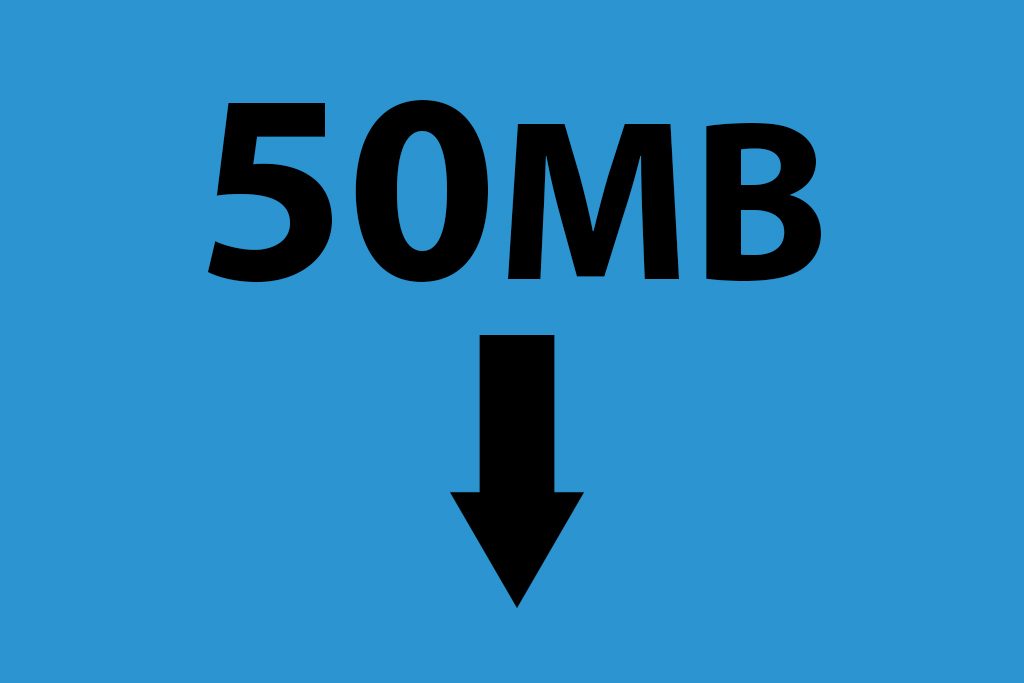
Occasionally, we receive files from clients that are above 25 mb’s in size, this is what we deem to be a high file resolution. Files that are sent to us above this limit have to be drastically reduced so that our printer is able to deal with them. As we print hundreds/thousands of items in 1 go, all file sizes combine together to create the build file. The higher this is, the longer the printers takes to process it. Our aim is to get the most amount of parts into the printer while keeping the file resolution as low as possible so we have to drop the resolution of individual files to achieve this.
Most people that send these files to us believe that the higher the resolution the better quality the part will come out. This is actually incorrect for 2 reasons. One, the printers layer resolution is 0.1 of a mm (100 microns), any details that are smaller than this, i.e. the size of each triangle in your STL file, are irrelevant as the printer will not print any smaller.
Two, the highest resolution files have to have the number of triangles in the file reduced heavily. A file that is originally 1 GB has to be reduced 40 times in our software, this gives us very little control over the final outcome and look of the file. Edges tend to be smoothed off, stopping the crisp right angles that are possible and triangulation appears on flat surfaces that travel up the Z axis. All of these are risks that are accepted by the client if the file is sent over our maximum recommended resolution of 25 mb’s.
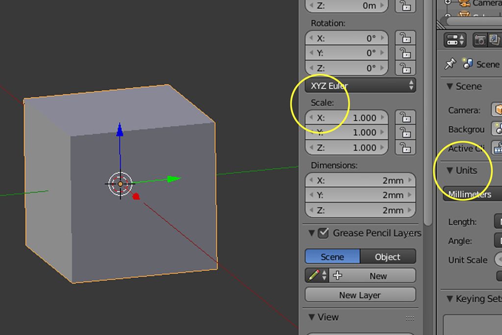
All parts MUST be saved in millimeters You are responsible for producing a print file to the correct scale. One of the biggest issues we have is clients EXPORTING stl files in the wrong scale – x 10 too small is the most common fault.
The reason why we no longer offer to scale client files is because scaling a part up will not add any new geometry to your model and this can lead to a reduced quality in print. Scaling an STL file will just scale the size of the triangles so it is far better for you to work to the right scale to ensure you get the resolution you require.
The dimensions of your parts are displayed on your quote below each file name for you to check. You are purchasing the file at that size only at that price.
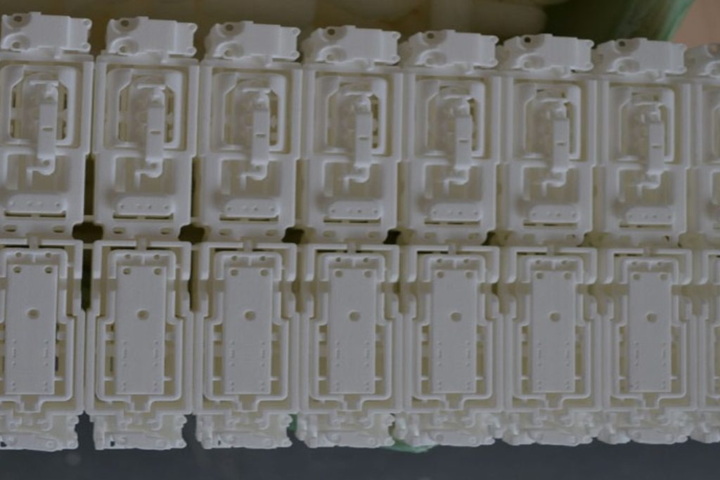
Sprues are used as a price reduction method when the number of bodies in the file, charged at £0.50 pence per body, is more expensive than the XYZ bounding box pricing. The sprues help to combat this by connecting all the bodies in the file to reduce the overall body count. It is not always necessary to connect every single body together to make 1 large connected body, you only need to join together enough parts to bring the average down to below 50p per body.
Sprued items DO NOT POLISH WELL. The will also leave white marks if they are dyed.
Sprues must be a minimum of 2mm in diameter all the way to the surface. Sprues that taper towards the end will be weak and may break in post-production. If sprues are below 2mm we will still print them, however, we are not responsible for parts that break off and get lost in the process.
Nesting your parts within the same physical space allows you to make the most of the money you spend on your prints. When it comes to printing those nested parts, we reserve the right to split up your nested parts to best place them within our print space. In this case, we will place the parts in the best orientation for the print rather than the most economical, resulting in a better print quality overall.
Nested parts must be a minimum of 1.5mm apart in all directions. Parts that are nested closer than this can fuse or affect the surface finish of the part.
Nesting is your responsibility – if your parts are overlapping or too close, they may fuse or have a poor surface finish. It is your responsibility to avoid this and we cannot be held accountable for errors caused by poor nesting.
We do our best to check the files that we print to spot any potential problems but ultimately the quality of your files falls on you. A few main offenders of Poor file quality includes low resolution, overlapping triangles, surface models (surface that have no thickness) and separate bodies.
File quality is your responsibility – if files are not one continual outer shell with no holes or overlaps then they risk printing inaccurately. We cannot be held responsible for these issues.
If a file is deemed unprintable or unfixable without physically modifying the file, you will be contacted regarding the issue. If this is the case, we cannot proceed with printing the order and it is put on hold until the issue has been resolved with either an amended file or written confirmation to proceed via email, with details of any file fixing where necessary.
3.6 Tolerance for Fitment
If you have two or more parts that are meant to fit together you will need to leave a tolerance for fitment. We recommend 0.2mm between surfaces. Anything below this will be printed, however, if below this we cannot be held responsible for parts that do not fit properly unless they are outside of our machine accuracy (see below).
3.7 Moving Parts
For moving parts, please leave a minimum of 0.5mm gap between moving surfaces. Anything below that can fuse and will not be covered for a free reprint.
As a personal recommendation, it is always better to print the parts separately and assemble after – you can achieve much better tolerances and we are able to orient parts better for a superior print quality.
3.8 Accuracy & Print Consistency
Machine precision is how accurately the machine can lay down the material to. This is commonly stated as the accuracy of the machine by many 3D printing companies, however should not be taken as how accurate your part will be. If an accuracy of 100μ* or 16 μ* from some higher resolution resin machines is stated, it is likely that that is the layer height (i.e. that is how high the layer on the machine is and not necessarily how accurate the part will be to the CAD model).
Our Machine Precision:
100 μ *
* (100 μ = 100 microns = 0.1mm)
Part accuracy is how accurate the part is once it has come off the machine and cooled down. These can be different as with all thermoplastic and/or heat processes, parts are susceptible to shrinkage and warping. Smaller parts between the size of a grape and the size of an orange are the most accurate. Larger and very tiny parts are worse.
Our Part Accuracy:
Spilt as a percentage of what accuracies we regularly achieve, and explained below why some parts do not reach this.
5%: better than 20 μ
94% of parts: up to 150 μ
Extreme Worst 1%: 1000 μ
Accuracy Guarantee:
Though we regularly print to a higher accuracy than our guarantee, we can only offer a guarantee of 0.3mm or 0.3% whichever is greater. Dealing with thermoplastics in a range of temperatures and states means that different parts can be affected in different ways that are difficult to predict, however, saying that, the majority of our parts come out within 0.1-0.2mm.
We do NOT guarantee large flat items against curving – please ask if you think that your parts may be affected.
Section 4: Order Details.
4.1 File Fixing
It is your responsibility to ensure your file is ready for print, however, in many cases, there will be errors. We fix all files before printing to ensure their success in printing, however, this is only for their printability and not their design. In some extremely rare cases, fixing can cause some features to be modified or deleted by our software and is extremely hard for us to identify. We cannot be held responsible for issues that arise from poor files during the fixing process.
4.3 Intellectual Property
You, as a designer, retain ALL your intellectual property rights in your 3D design, including without limitation any and derivative works like 3D renders. Except for the rights and licenses specified below, 3DPRINTUK shall NOT use, modify, display or distribute your 3D design or derivatives thereof. By uploading your 3D design, you warrant that it is either your original creation and not copied from any third party and/or entity or that you own the intellectual property rights of the design. You warrant that your User Generated Content will not infringe the intellectual property rights of third parties. Should your User Generated Content nevertheless be found to be infringing and/or in violation of any law, you will defend 3DPRINTUK against third party claims, and be held liable for all (direct and indirect) damages and costs incurred by 3DPRINTUK with respect to such claims.
We retain the right to review and refuse any order when it, in our own discretion, appears to infringe third party intellectual property rights.
We are happy to sign non-disclosure/confidentiality agreements where necessary.
4.4 Lead Times
Models must be paid for before printing commences. As soon as this is done your models will join the print queue and your turnaround time begins. We have a 3.00pm cut off for new orders. For orders placed after that time the turnaround will start from the next working day.
Lead times are not guaranteed
Express Service
- This is 2-4 working day lead time. 90% or orders will take 2 days, but we always allow 4 days in case of any problems that we may have during the print process.
- Express is exactly the same as economy, only you join the front of the queue and not the end.
- Cost 18p + vat per cm 3
Economy Service
This is an 7-12 working day lead time as an estimate.
The process is exactly the same material and quality as express, only you join the back of the queue rather than the front.
We print everything as quickly as we can, so it is likely is get to you before the estimate lead time, but please consider the lead time as it is stated.
Cost 11p + vat per cm 3
Higher Value orders:
For larger orders, please add 3 working days per £1,000 on the order. We will do our best to get them out sooner if we can, however please plan for additional time if ordering in bulk. We are able to send batches if some of the order is needed sooner.
In the case where a solid part has not be requested we reserve the right to hollow extra thick parts. We do this for the following reasons:
Print speed – If more of the Model is solid the print time increases as a result.
Reduce the risk of failure – Large areas of sintered nylon greatly increase the chance of a print failure.
Accuracy from banding – Thicker parts cause more surface banding.
The unused powder is trapped inside the hollow, so the part will retain the weight of a solid item. There are no air pockets within the part.
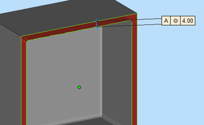
As standard, we use a 4mm wall but it is purely dependant on the part.
If want your (thick) part to be printed solid please request it in the notes box before checkout. This could increase your lead time by up to 5 working days. The reason for this increase is that we have to plan a specific build to deliver this process.
Solid production runs of large items will take considerably longer!