Machine Accuracy
Overview
In short, the majority of our parts are printed to around 0.1mm accuracy.
This is based on us regularly measuring parts that come off the machine and not based on what the layer height is. Previously we have not stated our exact accuracy as we do not believe that any 3D printer is consistently as accurate as the manufacturer stated layer height is, rather it can vary from model to model.
If you’d like to know more about why we choose to state it in this way and not just off the information we are supplied, please read the sections below.
Our Analysis:
Machine Precision Vs. Part Accuracy
Machine precision is how accurately the machine can lay down the material for each layer. This is commonly stated as the accuracy of the machine by many 3D printing companies, however this should not be taken as how accurate your part will be. If an accuracy of 100μm* or 16 μm is stated for some higher resolution resin machines, it is likely that that is the layer height (i.e. that is how high the layer on the machine is and not necessarily how accurate the part will be to the CAD model).
Our Machine Precision:
100 μm *
* 100 μm = 100 microns = 0.1mm
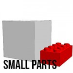
Part accuracy is how accurate the part is once it has come off the machine and cooled down. This can vary, as with all thermoplastic and/or heat processes, parts are susceptible to shrinkage and warping. Smaller parts — between the size of a grape and the size of an orange — are the most accurate. Larger and very tiny parts are worse.
Our Part Accuracy:
Spilt as a percentage of what accuracies we regularly achieve, and explained below why some parts do not reach this.
5%: better than 20 μm
94% of parts: up to 150 μm
Extreme Worst 1%: 1000 μm
Issues that make machine precision and part accuracy differ, why they happen and what we do to combat them
Parts affected:
Small holes
Roundness –
Holes facing up the Z axis are generally quite round, but holes less than 2mm can get powder blocked inside. Though the powder has not been melted, it may have been heated enough for it to become a bit stubborn! The best thing to do with it is to put a drill bit down it when you receive it.
Holes facing across the Z axis tend to be elliptical, especially when small (<5mm). This is because you are effectively building the hole from straight lines (the layers), so it is impossible to get a perfect circle. Imagine you are building a circle out of Lego and you’ll get the idea. Holes tend to be more elliptical on the top than on the bottom as the heat source cuts deeper through virgin powder than it does through sintered powder. We combat this with something called Z-compensation which raises the downward surfaces up by a few tenths of a millimeter but this is still not perfect.
Again, the best way to combat this is to put a drill bit through the holes once you receive them.
Deep Holes
Small diameter holes that run deep into a solid part tend to get clogged with powder as the heat from the solid part of the model radiates out and makes the powder in the holes pretty tough to remove. This can be a real problem with long twisting holes with a <5mm diameter. There is not really much we can do for these sadly.
For long straight holes, just as before, run a drill bit through and you should be fine.
Parts that are affected by this:
Shrinkage issues:
We automatically calculate the shrinkage amounts into the builds before we print. These are relatively complex as the lower half of the build can be hot for up to 24 hours longer than the top of the build. This means that larger objects will have been cooling for longer at the bottom than they will at the top. Most of the shrinkage rates are calculated in, so you cannot notice it for many parts, but if you have large parts that span the build volume, especially rectangular items, it can cause two types of problem:
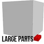
1. Very thick parts shrinking excessively
If you have very large areas of model per layer (8-10cm diameter plus) there is a large amount of hotter melted powder. This is likely to contract more than thinner parts. To combat this we hollow the parts, but leave the unmelted powder locked inside with a wall thickness of about 5mm. This results in a solid part that feels and weighs the same as a solid part and still has a lot of strength yet does not shrink as much as if it were completely solid. In some cases we build spars to maintain the shape if required.
Parts that are affected by this:
- Thick solid parts with a diameter greater than 10cm
2. Curve
This is because the outer peripherals of the build cool faster than the centre, and thus contract earlier than the middle. This causes the corners on the lower section only to shrink a little bit more than the centre and thus create a small curve on the bottom edge. This is not noticeable on smaller parts (less than 10cm across the bottom), but can be on larger parts.
To combat this we place dummy parts in the build around the corners of rectangular items. These are solid and therefore hot, and thus radiate heat around the corners for longer resulting in less shrinkage and therefore straighter and more accurate parts.
Parts that are affected by this:
- Large rectangular parts that are longer than 10cm across
Warping issues
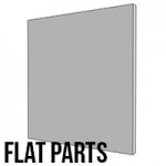
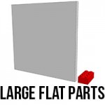
As with any heat process that is used to make flat parts, warping can be an issue. If you have large, thin, flat parts then it is likely that some areas will cool faster than others and thus shrink at different rates – i.e. if you’re making an A4 sized sheet that is 1mm thin, you’re likely to end up with a Pringle.
We combat this with a post process we do in house. This involves reheating the part and letting it cool clamped into position. We can only do this on parts that we are able to clamp so not all parts can be treated in this way. We’ll always try to warn you if there is the potential for your part to warp, and we’ll make sure we do everything in our power to avoid it. You must remember that if it does this with us, it is likely that it will do it with other processes!
Parts that are affected by this:
- Thin sheet parts that are wider than 15cm and less than 3mm thick.
Surface Powder
When the parts come off the machine they are caked in powder. We use a brush and an air compressor to blast the parts to remove this powder. Inevitably, considering we’re cleaning hundreds of models every day, there will be some cases where a bit of powder does get stuck in places like holes and grooves. The best thing to do is to get a toothbrush or poking utensil to remove the powder – you can use warm soapy water as well.
Surface Detail
Very small surface details that are below our minimum are not likely to come out. We have a recommended minimum of between 0.4mm and 0.5mm – below this and it’s at your own risk!
Parts affected:
Sharp angles
When you have a model that has a sharp edge, such as a blade or helix on a screw, you may find some inaccuracies with the part. This is due to the fact that the part needs to be sliced into 0.1mm cross sections. If you imagine a sharp trailing edge being sliced into layers, the final tip will not be there on the layer. if this is on the diameter of a round item or width of a square item, it is likely that your diameter/width will be reduced. The sharper the angle of the trailing edge, the greater the dimensional reduction.
You should be able to combat this by making the edge have a flat end. This will have to be done your end. It is suggested that you make this 0.4mm or greater.
If you would like to discuss any of these issues with us, please do not hesitate to contact us for advice.